DIY remote control based on PIC
v4.2 designed by Ceban Sergiu in 1985-2012
old version in December,2012
old version in December,2012
NOTE for beginners: PICs are general purpose microcontrollers which have to be programmed before you can use them in the actual circuit! Check out this link to learn more.
Control up to 8 devices by this easy constructable remote control. It can work as a radio or infrared remote control, depending on the components. Each device output can be configured to be momentary (turned on while you press the button) or latched. Latched outputs can be toggled on/off by one button per channel, or turned on and off by two buttons per channel.
 Try it now, before building! Click on the transmitter buttons with the green labels on the left and see how the receiver outputs (K1-K8) change. Change the number of transmitter or receiver channels. Switch the receiver output type between latched and momentary.
Containing a PIC microcontroller, the circuit is very flexible. You can decide which receiver outputs are latched and which are momentary. The Manchester-coded transmitter output is well suited for the cheapest ASK radio modules or for infrared control. The units are configurable to a unique address, which must match to control the devices.
Related project: 2^16 remote control encoder and decoder
If you have TTL signals to control remote digital output lines, please check this project instead.
If you have trouble with programming PIC microcontrollers, you can consider builing other circuits based on Holtek HT-12D, HT-12E, Princeton PT2262, PT2272 and Motorola MC145026, MC145027, MC145028 encoders/decoders.
Try it now, before building! Click on the transmitter buttons with the green labels on the left and see how the receiver outputs (K1-K8) change. Change the number of transmitter or receiver channels. Switch the receiver output type between latched and momentary.Containing a PIC microcontroller, the circuit is very flexible. You can decide which receiver outputs are latched and which are momentary. The Manchester-coded transmitter output is well suited for the cheapest ASK radio modules or for infrared control. The units are configurable to a unique address, which must match to control the devices.
Related project: 2^16 remote control encoder and decoder
If you have TTL signals to control remote digital output lines, please check this project instead.
If you have trouble with programming PIC microcontrollers, you can consider builing other circuits based on Holtek HT-12D, HT-12E, Princeton PT2262, PT2272 and Motorola MC145026, MC145027, MC145028 encoders/decoders.
4/8-channel V4.2 radio transmitter

The difference between the 4-channel and the 8-channel version is only the software inside. The 8-channel transmitter has one button (S1-S8) per channel. The 4-channel transmitter uses S1-S4 buttons to turn on, S5-S8 buttons to turn off channel 1-4 (use with latched outputs on the receiver). The D1-D4 diodes and J1-J4 jumpers are optional, and are used to setup the transmitter address. Higher supply voltage results higher transmit power, but V+ range is 2-5.5VDC for the PIC MCU. When V+ is higher than 5VDC, use separate power for the mcu.
Configure & download
What if you can't get a pic16f630?
Configure & download
What if you can't get a pic16f630?
- try a pic16f676, and put this line back into code:
clrf 0x91 ; ANSEL - try a pic16f628, here is the modified transmitter
4/8-channel V4.2 infrared transmitter

The difference between the 4-channel and the 8-channel version is only the software inside. The 8-channel transmitter has one button (S1-S8) per channel. The 4-channel transmitter uses S1-S4 buttons to turn on, S5-S8 buttons to turn off channel 1-4 (use with latched outputs on the receiver). The D1-D4 diodes and J1-J4 jumpers are optional, and are used to setup the transmitter address. V+ supply voltage should be between 2.5-5.5VDC. It is practical to use two or three AAA batteries.
Configure & download
Configure & download
4/8-channel V4.2 radio receiver
The difference between the 4-channel and the 8-channel version is only the software inside. The 8-channel receiver outputs are individually configurable for latched or momentary output. The 4-channel receiver has two outputs per channel: K1-K4 are latched outputs, K5-K8 are momentary outputs for the four channels. The "valid" LED shows the transmitter activity. Make sure to turn on all address switches when the transmitter diodes are absent, or the J1-J4 jumpers are cut. Choose V+ supply voltage between +6-15VDC, based on the relay voltage ratings. For 6V relays, use +6VDC, for 12V relays use +12VDC.
Configure & download
| please observe the corresponding address configuration! | |
 transmitter: no diodes connected |  receiver: switches all ON |
 transmitter: all diodes connected |  receiver: switches all OFF |
Configure & download

component pinouts
parts list
parts list
| part | description |
| C1, C2 | 22pF ceramic capacitor |
| C3, C5 | 100nF ceramic capacitor |
| C6 | 10uF 6.3V electrolytic capacitor |
| CN1-CN8 | PCB terminal block, 3-way (DG301) |
| D1-D8 | 1N4004 diode |
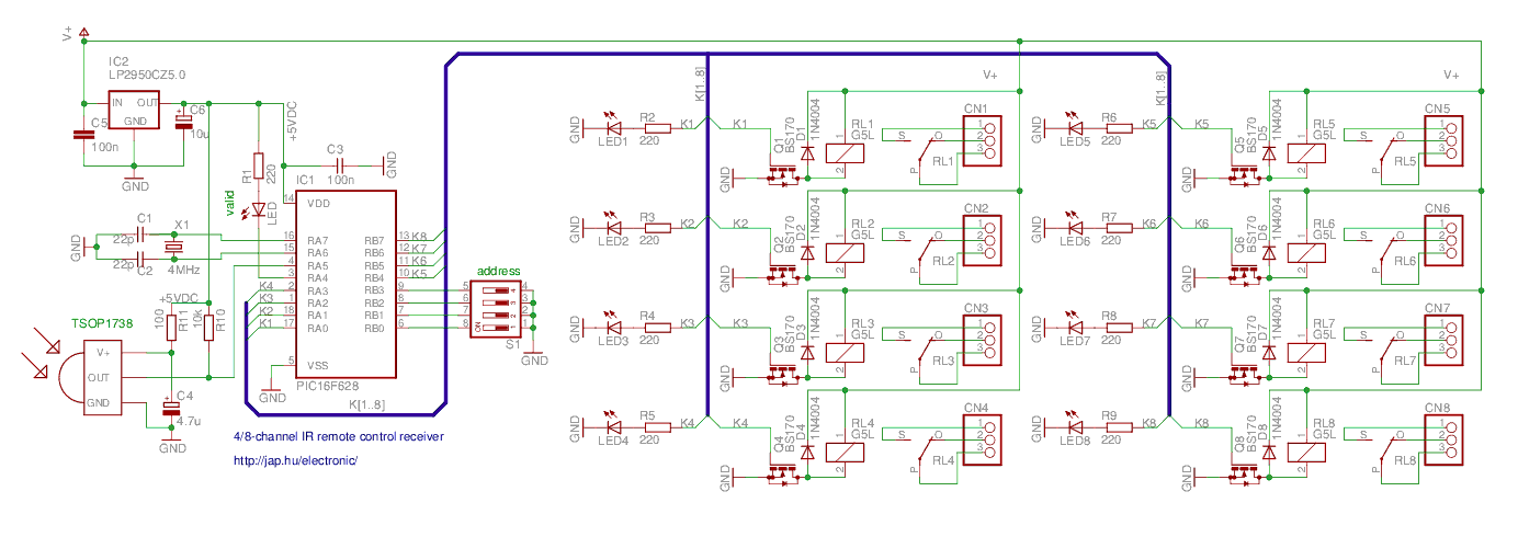
| IC1 | PIC16F627 or PIC16F628 or PIC16F627A or PIC16F628A |
| IC2 | LP2950CZ5.0 voltage regulator |
| LED | 3mm LED (green) |
| LED1-LED8 | 3mm LED (red) |
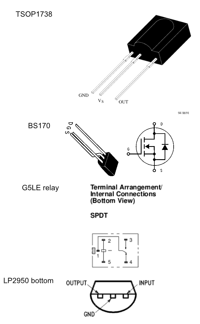
| Q1-Q8 | BS170 N-channel mosfet transistor |
| R1-R9 | 220R resistor (1/8W) |
| RL1-RL8 | G5LE relay, see text for coil voltage selection |
| S1 | piano DIP switch, 4-way |
| X1 | 4MHz HC49 crystal |
| RXMOD | 3-pin radio receiver module, see text (hardware) |
4/8-channel V4.2 infrared receiver
The difference between the 4-channel and the 8-channel version is only the software inside. The 8-channel receiver outputs are individually configurable for latched or momentary output. The 4-channel receiver has two outputs per channel: K1-K4 are latched outputs, K5-K8 are momentary outputs for the four channels. The "valid" LED shows the transmitter activity. Make sure to turn on all address jumpers when the transmitter diodes are absent, or the J1-J4 jumpers are cut. Choose V+ supply voltage between +6-15VDC, based on the relay voltage ratings. For 6V relays, use +6VDC, for 12V relays use +12VDC.
Configure & download
| please observe the corresponding address configuration! | |
transmitter: no diodes connected | receiver: switches all ON |
transmitter: all diodes connected | receiver: switches all OFF |
Configure & download
component pinouts
parts list
parts list
| part | description |
| C1, C2 | 22pF ceramic capacitor |
| C3, C5 | 100nF ceramic capacitor |
| C4 | 4.7uF 6.3V electrolytic capacitor |
| C6 | 10uF 6.3V electrolytic capacitor |
| CN1-CN8 | PCB terminal block, 3-way (DG301) |
| D1-D8 | 1N4004 diode |
| IC1 | PIC16F627 or PIC16F628 or PIC16F627A or PIC16F628A |
| IC2 | LP2950CZ5.0 voltage regulator |
| IC3 | TSOP1738 IR receiver, see text (hardware) |
| LED | 3mm LED (green) |
| LED1-LED8 | 3mm LED (red) |
| Q1-Q8 | BS170 N-channel mosfet transistor |
| R1-R9 | 220R resistor (1/8W) |
| R10 | 10k resistor (1/8W) |
| R11 | 100R resistor (1/8W) |
| RL1-RL8 | G5LE relay, see text for coil voltage |
| S1 | piano DIP switch, 4-way |
| X1 | 4MHz HC49 crystal |
software
All the devices use new, FLASH-based microcontrollers, this means that they can be re-programmed many times. You can experiment with the source code settings to fit your needs. The code must be compiled as a linked project under MPLAB. Please check FAQ at the PIC page.
Please note that the decoder package contained a non-functional HEX file, which has been corrected as of 2nd Jul, 2010. If you ran into this problem, the receiver could be made to work by compiling the source code. Sorry for the trouble.
A bug in the 8-channel decoder package was corrected on 16th Mar, 2012. When using channel 5, the valid LED indicator was handled incorrectly.
| source file | line | meaning |
| enc-042.asm | 25 #define MODE_CH4 | the device is 4-channel, sending ON/OFF channel codes |
| enc-042.asm | 28 #define MODE_CH8 | the device is 8-channel, sending simple codes for channels |
| irmtxv4.asm | 44 pwm_freq EQU d'38000' | the IR transmitter frequency is set to 38000 Hz. This should match the receiver module frequency |
| dec-043.asm | 36 LATCH_MASK EQU 0xff | select outputs to be latched. This is a binary mask, one bit per channel. Other channels will be momentary Example: LATCH_MASK EQU B'00001111' # channel 1-4 are latched, channel 5-8 are momentary |
| dec-044.asm | 38 LATCH_MASK EQU 0xff | |
| mrxv4.asm | 56 #define SKL btfsc 57 #define SKH btfss | normal decoder logic input is used for the RF receivers (most times) |
| mrxv4.asm | 60 #define SKL btfss 61#define SKH btfsc | inverse decoder logic input is used for the IR receivers (most times) |
hardware
The radio version circuit diagrams show generic ISM RF modules, which connect to the circuits using two power pins and one modulation pin. The transmitter (TX) module is connected to the transmitter circuit. The receiver (RX) module is connected to the receiver circuit. Choose ISM RF modules from the list of modules. The remote control works with the cheapest OOK/ASK modules and with FSK modules, too. Use the same frequency and modulation type for all modules. Choose a module which doesn't need setup - these are which connect only using 3 pins (ground (GND), power supply (VCC), modulation in/demod out (MOD) ) and usually have an external antenna (ANT) connection.
If you are building the infrared version, choose an IR LED matching the wavelength of the receiver module. The receiver center frequency should match the transmitter modulation frequency, which can be set the transmitter source (pwm_freq). If in doubt, just choose a TSOP1738. A list of usable modules: Sharp GP1U52X, IS1U60L, Vishay TSOP17XX, TSOP18XX.
If you are building the infrared version, choose an IR LED matching the wavelength of the receiver module. The receiver center frequency should match the transmitter modulation frequency, which can be set the transmitter source (pwm_freq). If in doubt, just choose a TSOP1738. A list of usable modules: Sharp GP1U52X, IS1U60L, Vishay TSOP17XX, TSOP18XX.
FAQ
Q: Do I have to use a bs170 transistor in the receiver?
A: You can use other logic N-channel mosfets or npn bipolar transistors (with a series base resistor added) to drive the relays in place of Q1-Q8 of the remote control receiver. Examples: bss138, bc182+2.2kohm
Q: How do I set toggle or momentary mode for the relays?
A: Make a modification in the receiver source code. Modify the LATCH_MASK define - this contains one bit for every channel. A zero bit sets the corresponding output to momentary, a high bit sets the corresponding output to latched. For example, the line
Q: I want to control multiple outputs by pressing button 2 and 3 at the same time. Is that possible?
A: Not with this project. Please use this 2^16 remote control encoder and decoder instead.
Q: What if I can't get a pic16f630?
A1: Try a pic16f676, and put this line back into code:
A2: Try a pic16f628, here is the modified transmitter
Q: What radio modules can this remote control work with?
A: You can choose from this list. The remote control works with the cheapest OOK/ASK modules and with FSK modules, too. Use the same frequency and modulation type for all modules. Choose a module which doesn't need setup - these are which connect only using 3 pins (ground (GND), power supply (VCC), modulation in/demod out (MOD) ) and usually have an external antenna (ANT) connection.
A: You can use other logic N-channel mosfets or npn bipolar transistors (with a series base resistor added) to drive the relays in place of Q1-Q8 of the remote control receiver. Examples: bss138, bc182+2.2kohm
Q: How do I set toggle or momentary mode for the relays?
A: Make a modification in the receiver source code. Modify the LATCH_MASK define - this contains one bit for every channel. A zero bit sets the corresponding output to momentary, a high bit sets the corresponding output to latched. For example, the line
LATCH_MASK EQU B'00001111'sets channels 8-5 to momentary and channels 4-1 to latched (toggle) mode. Then use the compiler (MPLAB or gputils) to assemble the code.Q: I want to control multiple outputs by pressing button 2 and 3 at the same time. Is that possible?
A: Not with this project. Please use this 2^16 remote control encoder and decoder instead.
Q: What if I can't get a pic16f630?
A1: Try a pic16f676, and put this line back into code:
clrf 0x91 ; ANSELA2: Try a pic16f628, here is the modified transmitter
Q: What radio modules can this remote control work with?
A: You can choose from this list. The remote control works with the cheapest OOK/ASK modules and with FSK modules, too. Use the same frequency and modulation type for all modules. Choose a module which doesn't need setup - these are which connect only using 3 pins (ground (GND), power supply (VCC), modulation in/demod out (MOD) ) and usually have an external antenna (ANT) connection.
references
- list of ISM RF modules
- TSOP17XX infrared receiver IC datasheet
- General info about PIC microcontrollers and their programming
- Microchip PIC16f630 PIC16f684 PIC16f628 microcontroller datasheet
- Microchip MPLAB development environment for the PIC devices
- GNU tools for PIC development
- mc145026 mc145027 mc145028 datasheet


Комментарии
Отправить комментарий